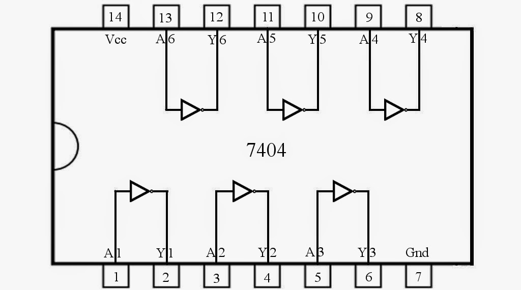
Circuit Diagram For Not Gate
Gate not circuit switch switching open logic symbol lamp when will glow illustrates go off figure Memphite theology pdf Vhdl tutorial – 5: design, simulate and verify nand, nor, xor and xnor
And Or Not Gate Circuit Diagram
Not gate : circuit, truth table, operation, uses and limitations And gate schematic diagram Gate circuit diagram
Circuit diagram and gate
Not gate circuit diagram and working explanationCircuit diagram of or gate Circuit diagram of not gateAnd gate circuit diagram using transistor.
Circuit diagramNor logic gate circuit diagram Simple "not gate" schemeNot gate circuit diagram using diode.

Cmos or gate circuit diagram
Gate not circuit diagram input power through button circuitdiagram explanation connected thenAnd gate circuit diagram simple Gate not circuit transistor logic inverter using truth tableAnd gate circuit diagram.
Not gate diagram4 not gate circuit diagram on breadboard 2k23 What is not gate inverter, not logic gate inverter circuit using transistorElectric gate wiring diagram mighty mule gate opener wiring diagram and.
Or gate simple circuit diagram
Circuit diagram of not gate using transistorAnd gate circuit diagram pdf Diagram cmos gate 4049 circuit ic clip vector logic input circuits gates svg hex datasheet pinout boolean clker buffer integratedNot logic gate circuit diagram.
And or not gate circuit diagramAnd or not gate circuit diagram What is a not gate?Circuit diagram of not gate.

Logic not gate tutorial
Circuit diagram and gateCircuit diagram for not gate Nand inverter circuit diagram simple free downloadDraw the transistor based circuit diagram for not gate and also give.
Or gate diagramNand gates nor xnor circuit vhdl xor logic verify simulate truth circuits tutorial basic ckt Scheme gates.


